Design-and-Use-of-Relational-Databases
Content and Goals
ER (Entity Relationship) model is a conceptual model of a database, created after we are aware of our databases requirements but before the database is implemented. One of its main benefits is that we can use terminology familiar to the client in creating a high-level structured model of the database. In ER model we define the databases entities, their relationships, associations and interactions between entities. The idea is to be able to model all the requirements of different user groups. The client can still affect the model at this point and fix possible mistakes or missing information.
Our learning goals for this tutorial are:
- Basic terminology of ER modelling
- Recognition of the symbols used in ER diagrams
- How to define entities with different attributes
- Ability to understand simple relationships between entities
ER model is based on modelling the information stored in the database by using entities, attributes and associations (that is, relationships).
Entity, Attribute and Relationship
Entity is an independent object existing in the real world. Entities can be both physical objects and abstract concepts.
- Examples of physical entities: a student, car, employee
- Examples of abstract conceptual entities: a bank account, university course
- Entities are often represented by nouns. Answers to questions what or who
Attribute is a property of an entity. An entity can have multiple attributes but one attribute always describes a specific entity. Even if another entity’s attribute would have the same title.
- Attributes can be simple (first name) or composite (address consisting of street, number and so on)
- Primary key attribute is an attribute or a group of attributes that uniquely identifies an entity
- Attributes are often represented by nouns and they define one feature of the entity
A relationship is an association between entities.
- For example, many students participate on a course, many teachers work in ICT department, a lecture is given in a class room
- There are different types of relationships depending on how many instances of an entity are in relationship with the associated entities.
- The relationships can be: one-to-one (1:1), one-to-many (1:N), many-to-many (M:N)
- Relationships are often represented by verbs that describe how the entities are related
Task 1: ER model concepts
The purpose of the task is to classify things in the university world using the concepts of the ER model: entity, attribute and relationship. Please select and drag university concepts to correct category (in ER model)
ER diagram
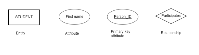
ER diagram is a presentation of the structure of the database, not the actual data. The data type or the domain of the attributes are not included. The basic symbols of ER diagram represent entities, attributes, relationships and their different forms.
- The names of the entities are presented in singular forms
- The names of entities and relationships are written in all capital letters
- The names of attributes are written with the first letter capitalized
Task 2: ER symbols
Task 3: ER symbols
The purpose of the task is to identify the symbols of the basic elements of the ER model (entity, attribute and relationship) in the diagram.
Attributes
The properties of an entity are called attributes. For example, name, age, social security number, student number, address and phone number are typical attributes associated with a student.
In relational database the attributes would be the columns (or fields) of the table named after the entity. Without attributes the entities have no identity or meaning. An entity with only one attribute and only one relationship would be better represented as an attribute of another entity.
Every typical entity has a key attribute or a collection of attributes that forms a key. This/these key attribute(s) uniquely defines the instances of a given entity. In order to distinguish the entities of a given entity type from each other, the values of the key attribute need to be unique for each instance of the entity. Sometimes we cannot form a unique key for the instances by using just one attribute. In these cases we need to form the key as a collection of multiple attributes in such a way that the values of those attributes uniquely defines every instance of the entity. Exception to this are the so-called weak entities. The weak entities cannot be uniquely defined by their own attributes. They need an attribute from another entity (so called foreign key) to be uniquely defined. We will get back to this later on the course.
Notice that relationship in ER model and relationship in relational database mean different things. In a relational database the relationship means a table with all of its fields (so, the attributes that present an entity) but in ER model a relationship is an association between two or more entities. This kind of relationship would in a relational database be represented by a foreign key (key attribute of another entity, will be discussed later).
An attribute can be:
Simple or composite The value of a simple attribute cannot be subdivided (for example, age). Most attributes are simple. The composite attribute can be subdivided for additional attributes (for example, an address could be subdivided to street name and number.) Single or multivalued Single-valued attributes only have a single value at a time. Most attributes are single-valued. Multivalued attributes can have several values at a given time. (For example, person’s degrees) Stored or derived The value of a stored attribute cannot be concluded from other attributes. (For example, a person’s home address) The value of a derived attribute is calculated based on other attributes and/or other information (for example, person’s age could be derived by knowing the person’s date of birth and the current date.) Derived attribute could also depend on the whole entity type (for example, the number of students could be derived by counting the records in student table.) Key or composite key An entity has one or more key attributes that identify each instance. The goal is to minimize the amount of attributes needed for the key. (for example, first name and last name could form a composite key if there are no other instances with the same name.) The key attribute or the composite key needs to be unique for each instance of the entity. Complex Complex attribute is an attribute that is formed as a collection of composite and multi-valued attributes. For example, a person has multiple apartments which each has possibly multiple phone numbers. An entity may have such attributes that their value in some instances of the entity does not exist. The information and the lack of that information can however be meaningful, so this attribute needs to be in the model. An attribute whose value can be null cannot be used as a key or part of a composite key.
Task 4: Attributes
Organize the attribute related concept and its definition/explanation.
Differences in attribute symbols
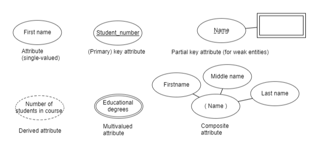
An attribute is a good example of how a concept in ER-model may have different versions of symbols representing it depending on the spesific use case. An attribute is represented by an ellipsis which is connected to an entity to which attribute it is. The text inside the ellipsis is underlined if the attribute is a key. If the attribute is a composite key, the text inside the ellipsis is underlined with a dashed line. If the attribute is multivalued, the edge of the ellipsis is drawn with a double line. If the attribute is derived, the edge line is drawn as a dashed line. Composite attributes are represented by a single attribute connected to the entity. The attributes that the composite attribute consists of are connected to the composite attribute with lines of their own.
Task 5: Find different attribute symbols
There are several different types of attributes. The purpose of this task is to identify the symbols that represent them on an ER diagram.
Relationships of Cardinality 1:1 and 1:N
One-to-one and one-to-many
In an ER-model every entity is associated with at least one other entity via relationship. These relationships are mostly binary (between two entities) but it is possible to have more than two entities associated to each other with a single relationship. It’s often useful to explicitly define the cardinality (or multiplicity) of the entities associated with the relationship. The cardinality affects both how the database is used and how it is implemented.
The cardinality of a binary relationship defines how many instances of the entity can be associated with the relationship.
For example, the relationship between a person and a date of birth has cardinality one-to-many. Each person has only one date of birth but each date of birth can be related to multiple persons.
The cardinality of a relationship can be open to interpretation and it can be dependant on how the database is going to be used in practice.
In one-to-one relationships (1:1) every instance of an entity is associated with at maximum one instance of the other entity through that relationship.
In one-to-many relationships (1:N) every instance of an entity can be associated to multiple instances of the other entity through the relationship.
Task 6: Defining relationships based on the context description
One-to-one relationship
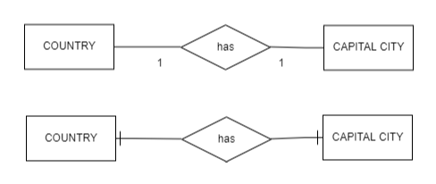
Drawing a binary one-to-one relationship can be thought of as similar to reading a sentence representing the relationship. That is, we begin by one of the entities on the left side and we say that one instance of the other entity is associated with it. We draw a diamond between the rectangles representing the two entities. Inside the diamond we write the verb that represents the relationship. We then connect both of the entities to the diamond with a line. Then we follow the line from the first entity to the diamond and write the number 1 to the opposite side (right) of the diamond describing that the relationship is to one instance of the right side entity. Then we look at the relationship from the right side entities point of view and notice that exactly one instance of the left side entity is associated with the entity. Thus, we draw a number one also on the left side of the diamond.
Then if we read the relationship in the example below, it could be worded as: “A country has one capital city, and a capital city has one country”. If we are exact, we could say that “a country has maximum one capital city at a time, and a capital city has maximum one country at a time”. So, these values are representing the maximum number of relations to the other end. (In the next page, we are going to discuss minimum i.e. mandatory and optional participation).
There are few different ways to mark cardinalities to relationships. Above a numerical notation/style was instructed. However, in this course we use (mainly) a style called ‘crow’s foot notation’. (The N-side looks like a crow’s foot while 1-side is just a cross line). Below are representations of both notations. Important is that you learn how to read the relationship and (later) know how it effects on the database implementation. If you learn to read and create relationships with one notation style, you manage all other as well.
More examples of Crow’s foot notations can be found for example in here: https://www.freecodecamp.org/news/crows-foot-notation-relationship-symbols-and-how-to-read-diagrams/
One to Many relationships
Let’s define how to draw a binary one-to-many relationship in a similar way. Let’s begin with the left hand side entity and say that it is associated with many instances of the right hand side entity. Again, we draw a diamond between these two entities and write a verb represetngin the relationship. We connect both the entities to the diamond with lines. Now, looking from the left side entities point of view there are N instances of the right side entity that are associated to it by the relationship. Thus we draw the letter N to the right side of the diamond. If we then consider the right hand side entity, we draw the number one to the left side of the diamond depicting that there is only one instance of the left side entity that is related to an instance of the right side entity. Because the relationship is not symmetrical we might have to begin with the right side entity. The principle of how to draw the diagram doesn’t change.
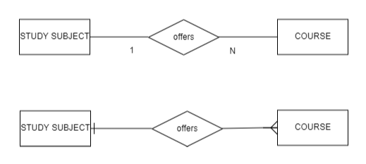
Note! In 1:N relationships make sure that the direction of the cardinality is correct. This can be done by reading the relationship from the direction of each entity separately.
Task 7: Read the description and select ER model with correct cardinality (1, 2 or 3)
Participation constraints (total / mandatory)
The participation constraint of a relationship tells us if the existence of an instance of an entity type is dependant on a relationship with an instance of another entity type.
For example, can a company have an employee who isn’t in any department.
Participation constraint can be either total or partial. If the constraint is total, every instance of the entity must participate in the relationship with another entity in order to exist. Total participation constraint is also called existence dependency. Total participation is also referred as mandatory.
In ER diagrams the total participation constraint is drawn
as a doubled line in the beginning of the relationship: Picture 1 below as a cross line in the end of the relationship (in crow’s foot notation): Picture 2 below Both ER diagrams can be read (from the viewpoint of the LECTURE-entity) in the following ways: - Lectures are associated with one course and without the course they cannot exist. - An instance of a lecture has one and only one instance of course-entity it is associated to.


Participation constraints (partial / optional)
Partial participation constraint, on the other hand, is such that not all of the entity’s instances necessarily participate in the relationship. Partial participation is also referred as optional.
When reading the above ER diagram from the viewpoint of the COURSE-entity, we have a partial participation:
A course may have many lectures or not at all. Partial participation constraint is drawn in ER diagram (see the example diagrams above)
as a single line in the beginning of the relationship as 0 in the end of the relationship (in crow’s foot notation) From now on, we will use only crow’s foot notation in ER diagrams. You may have noticed that in this notation first is shown the participation constraint (as 0 or crossed line for optional and mandatory participation), and second the maximum amount of relations (as a crossed line or crow’s foot for 1 or Many). One of the benefits of crow’s foot notation is that you can read both minimum and maximum participation from the same end.
The same participation constraint doesn’t necesarily exist in the reverse direction of the relationship.
Example diagram

Read: Every department needs a department head who manages the department, even if not all employees need to be heads of a department. A department has one and only one manager, and employee can manage only one department.
The relationship can be partial (optional) in both directions:
Example diagram
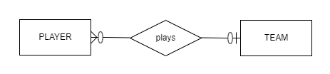
Read: A football player may not have a contract to play in any team (zero in the TEAM end) and the maximum number of teams the player can play is one (a crossed line in the TEAM end). Similarly, a football team may not have any contracts for players and nobody is assigned to a team (for example, if the team is newly created) (zero in the PLAYER end). However, a team may have many contracts made with players (crow’s foot / fork symbol in the PLAYER end).
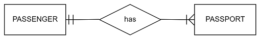
The relationship can be total (mandatory) in both directions:
Example diagram
Task 8: Constraints
Identify whether all instances of an entity participate in the relationship. Please note that the participation is entity-specific, i.e. pay attention in defining relationships from the perspective of both parties.