Design-and-Use-of-Relational-Databases
Content and Goals
In this tutorial we continue the discussion about ER-models by looking into many-to-many relationships, weak entities and designing and drawing an ER model.
In this tutorial we will learn:
- Many-to-many relationship and representing them in ER-model
- Weak entity
- Creating an ER-diagram
Many-to-Many relationship
In the ER-model every entity type is associated with at least one relationship. In practice, if you see (or create) an ER model for relational database, no entity must remain isolated, but each must have at least one connection.
In most cases the relationships are binary (between two entities) but it is also possible to have relationships between multiple entities. It’s often necessarily to explicitly define the cardinalities of the entities associated by a relationship. The cardinality affects both the use and implementation of the database.
The cardinality of a binary relationship dictates the number of instances with which the entities are participating in the relationship.
The cardinality can be subjective and dependant on how the database is expected to be used.
Learnt before: In one-to-one relationships (1:1) every instance of the first entity can relate to at most one instance of the second entity. Similarly every instance of the second entity can relate to at most one instance of the first entity.
Example: Faculty-Adminstration relationship is one-to-one. Faculty is led by one adminstration and one adminstration can lead only one faculty.
In one-to-many relationship (1:N) every instance of the first entity can relate to one or more instances of the second entity but an instance of the second entity can not be related to more than one instance of the first entity.
Example: Faculty-Department relationship is one-to-many. There are multiple departments in a faculty but a department belongs to exactly one faculty.
New:
In many-to-many relationship (M:N) every instance of the first entity can be related to more than one instance of the second entity. Similarly, every instance of the second entity can be related to more than one instance of the first entity..
Example: Student-Course relationship is many-to-many. A student can participate in many courses and a course can be participated by many students.
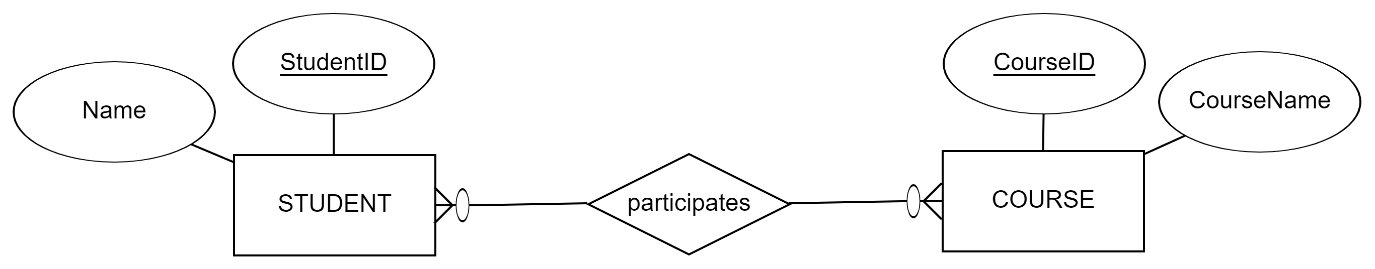
Let’s consider drawing a many-to-many relationship in crow’s foot notation. As learnt before we begin by drawing the entities. Between the entities we draw a diamond and write a verb inside it to represent the relationship between the entities. We connect both of the entities to the diamond with single lines. Next we consider the left entity’s cardinality. As this is a many-to-many relationship, this many instances of this entity participate in the relationship. So we draw a crow’s foot connected to the left entity. Similarly for the right entity.
In addition, in crow’s foot notation we also need to consider the participation constraints of the relationship. If the relationship is mandatory, we draw a cross line next to the crow’s foot and if the relationship is optional we draw a 0.
In the above diagram, a student does not have to enroll to any course and a course may not necessarily get any enrollments. The justification for optional participation i nthe both ends comes from a real world situation: It could be that the courses has just been published ( a second ago) and the student have not yet enrolled (but will in the next coming weeks).
Another example of M:N relationship:
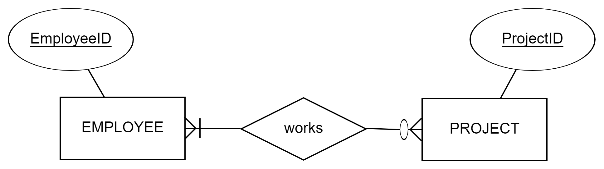
Reading the ER-diagram above: An employee of the company participates in several projects (e.g. during the year), and several employees participate in the project. The employee does not have to be in any project (e.g. CEO of the company). The project must have at least one employee.
So, in practice, we could record data that (responds our information needs in the following way):
- John works in projects X, Y and Z,
- Mike works in projects X and Y,
- Z-project has only one worker (John),
- X- and Y-projects have two employees (Mike and John) - David does not relate to a project at all
These videos recap previous information
Attributes in relationship
We can add attributes not only to an entity but to any relationship as well. This is quite common especially in many-to-many (M:N) relationships. Next, we will discuss why, and consider its limitations.
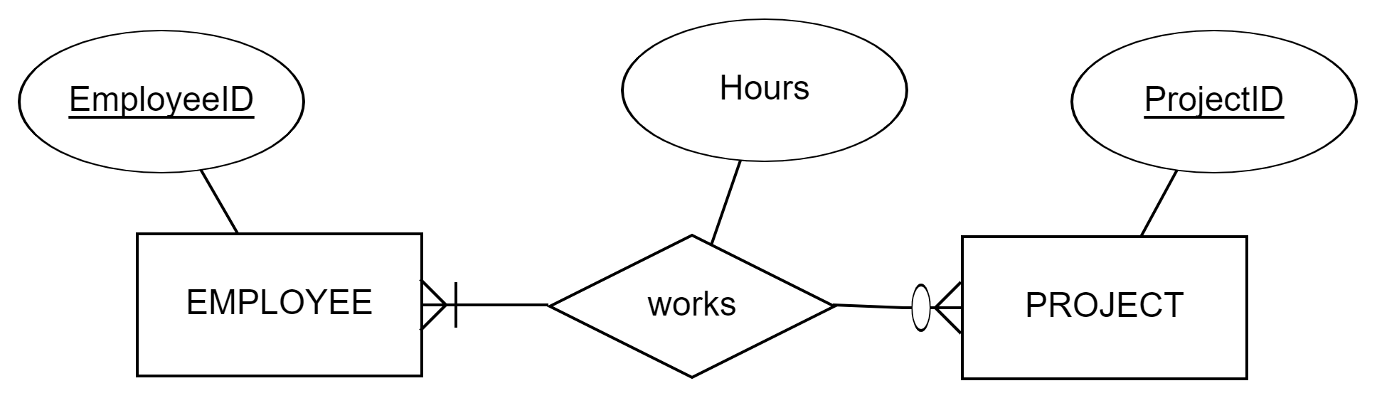
Consider the previous diagram about Employee-Project -relationship. It satisfies the need for information about which projects this employee work and which employees work in this project. However, if one would like to know how much (many hours) employees have worked in their projects or vice versa, we are missing an attribute to store that data.
So, let’s add an attribute called ‘Hours’ to the diagram that could store a numerical value denoting the number of working hours done by the employee for the specific project. But where to put it: to the entities or to the relationship?
In the Employee-entity, Hours-attribute would store only one value (e.g. 23h) for each person (employee-instance), which means that, for example John, who works in three different projects would not know hours for his projects separately. Thus, Hours-attribute would store kind of a ‘total hours for all his projects’, which is fine for that purpose, but not in the level of detail required (hours for specific project). The same holds for the Project-entity: Hours-attribute would store one value meaning ‘total hours of all employees working in the project’.
The solution is that the information need lays in the relationship between a specific employee and specific project. Hours-attribute is a characteristic of the relation between the employee and the project. For example, John has worked 23 hours in the project X, 78 hours in the project Y, and 0 hours in the project Z. In the project X, John has worked 23 hours, and Mike has worked 54 hours. Each time the employee and the project are connected we add information about the hours.
Next example describes product orders. In the database, we would like to store our products with their product numbers, names and prices per unit. Considering one specific product (e.g. a bottle of cola drink), that has been ordered many times or none. Many times, as our grocery store has thousands of those cola bottles sold, and none (optional), as the product may be new in our selection (e.g. new cherry-vanilla taste) that we have not sold yet. Each time the product is related to an order, we store data about what was the quantity of the bottles, possible discount percent and the actual selling price of one unit (bottle). From the viewpoint of one Order, many-to-many relationship is defined as mandatory: There is no order without a related product. One order can contain many different products, and for each, the attributes of the relationship tell how many pieces and what was the selling price.
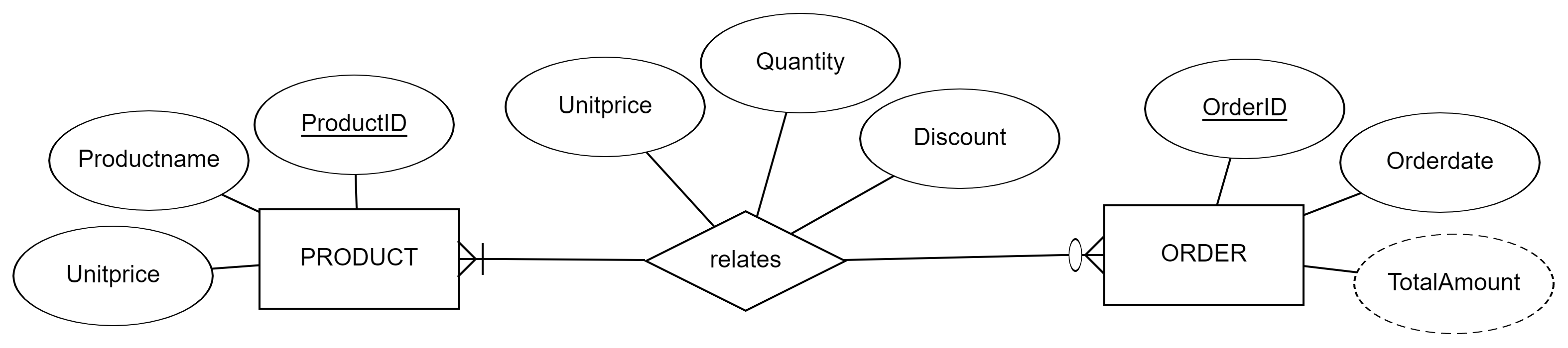
So, we can get information such as
- 300 cola bottles with selling price 0,50 dollars and discount 0 % were ordered with order number 333 in 12.5.2023 having total amount 150 dollars.
- 25 cola bottles with selling price 1,00 dollars and discount 0 % were ordered with order number 877 in 16.5.2023 having total amount 400 dollars.
- In the order number 877, three different products were ordered: 25 cola bottles (see above), 100 bottles of still water, and 500 bottles of ice tea (with specific unit prices and discounts).
- The order number 333 holds only one product (see above).
- The cherryvanilla taste cola bottle with productid 99 has not any related orders.
Limitations
Attributes in relationships do not have primary keys. Primary keys are defined only for entities. This means also that specific instances of participating entities can relate to each other only once.
Let’s consider two ER diagrams above. In the first diagram, we stored information that John has worked 23 hours in a Project X. There is no need, or possibility, to store that same information twice. In the same way, the second diagram says that the order number 333 contained 300 bottles of cola. We are not able to relate the same cola bottle products to the same order number twice, and there is no need to do that.
Therefore, many to many relationships and the related attributes are usable in situations when participating instances relate only once. Sometimes this is a limitation, and you should be able to identify situations when you need an entity instead of relationship with attributes. In the next tutorial we are discussing about relational model and how to transform ER model to a relational model. Relational model does not have many to many relationships and all these relationships in ER model are extracted to 1:N or 1:1 relations by adding an entity/relational table between original entities. Some designers consider this limitation, or implementation reality, already when modeling ER diagrams.
Before going into details of relational models, we turn our view on a new concept of weak entity and last creating and drawing ER models.
Weak entity
An entity without its own key attributes is called a weak entity. That is, a weak entity cannot be uniquely identified by its own attributes.
Instances of weak entities can only be identified by association with their identifying or owner entity. The participation constraint of the identifying relationship is always complete for the weak entity. That is, each instance of the weak entity needs to be associated with an instance of the owner entity.
In ER-model the weak entities are indicated by double-lined rectangles. The relationships that identify the weak entities are also indicated as double-lined diamonds.
A weak entity often has a partial key with which its instances can be identified when the owner instance is known. In the worst case, the partial key may constitute of the set of all of weak entity’s own attributes.
The attributes that are part of the partial key are underlined by a dashed line.
Examples of weak entity:
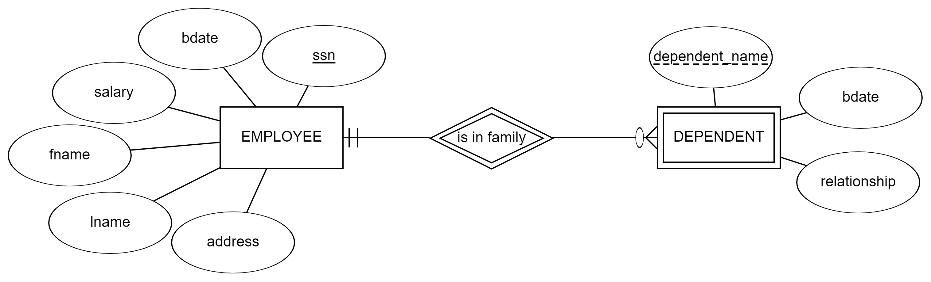
We want to store our employees and their family members and relatives in our database. An employee’s family member can be identified by their name, if we assume that the employee doesn’t have two family members with the same first name. We also need to assume that the same family member is not associated with more than one employee. In this case, the family member’s first name works as a partial key. Dependent is identifiable only by knowing employee’s ssn (social security number). Dependents can have same names but not within the same employee.
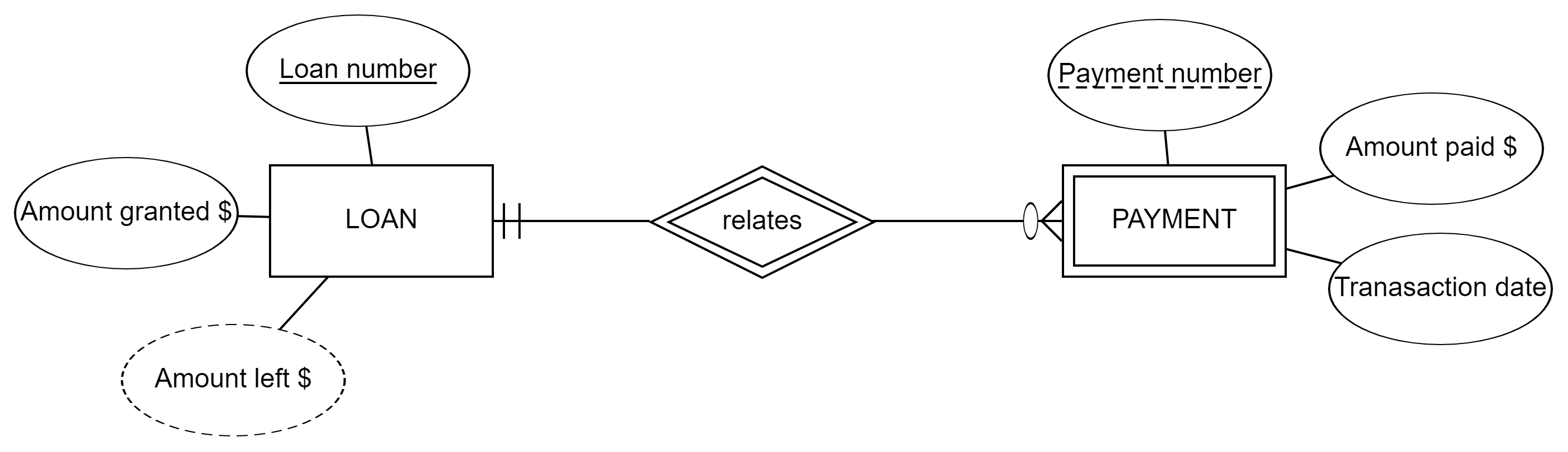
Loans have several payments that shorten the loan amount. Payment is defined here as a weak entity, because it is not identifiable without getting information about the specific loan it is a payment of. Payment_number is the partial key, meaning that the database can have e.g. payments numbered from 1 to 25 which relate to a house loan and payments numbered from 1 to 15 which relate to a car loan. Values of partial keys can be the same, but the detailed identification is got from the loan and its number.
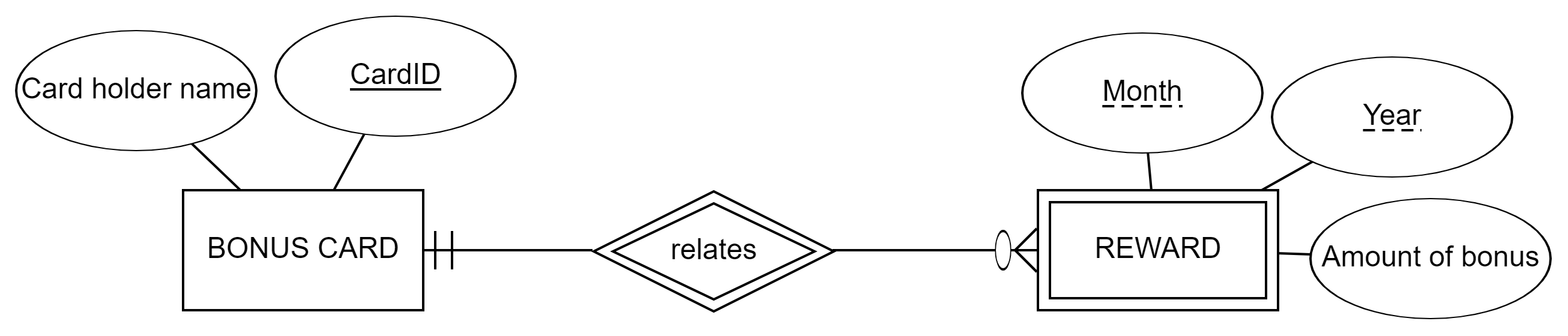
Grocery chains have applied bonuscards that give the consumers monthly rewards (discounts etc.). Reward is defined here as a weak entity with a combined partial key (month, year) which separates different rewards from each other under the same bonuscard.
Weak entities in practice
When implementing the model we can sometimes avoid the use of weak entities by adding its attributes as a multivalued composite attribute of its owner entity. However, it is recommended to use the weak entity instead of a multivalued attribute if there are “enough” attributes that are part of the weak entity as it would become increasingly difficult to handle the multivalued attributes. The same applies if the weak entity would have relationships with other than its owner entity.
Use of weak entities may bring unnecessary complexity to ER models, and there are rare situations when weak entities are truly necessary in real life design. A common mistake with weak entities is that weak entity is confused with total / mandatory participation of a relationship and used in that purpose. For example, above weak entities could have been modelled as ‘normal’ entities, of course eventually depending on the contextual information needs: We could attach each dependent an artificial ID, a numeric value that is unique for each dependent, and having that DependentID the Dependent entity, as a normal entity, still has a mandatory relation to one and only one employee. Similarly, Payment with its own primary key has to relate to one and only one loan.
Therefore, we do not recommend using weak entities in the beginning of your database design career, although it is good to know that solutions exist. Weak entities are good for situations where we have a domain concept with several attributes (entity) but need for a primary key in relation to other entities (weak).
Creating and drawing ER diagrams
Summary of ER modeling technique:
ER-model is a conceptual model of a database, created after we are aware of our databases requirements but before the database is implemented. One of its main benefits is that we can use terminology familiar to the client in creating a high-level structured model of the database. In ER model we define the databases entities, their relationships, associations and interactions between entities. These are represented by entities, attributes and relationships. It’s often easier to see the big picture by looking at the diagram. However, interpreting the diagram requires knowledge about the substance being modelled.
Below we list some universal design tips and common difficulties for beginners based on our experience with ER models. In the end, it is your modeling and implementation context that determines how good the plan will be in practice.
Design tips for ER models
Tip 1: Think who is your client, what is the purpose of database, and whose data management you are planning to support. Usually, this is not an entity in your diagram. You need to model only what is ‘inside’ that target domain.
-
Remember, that an entity needs to have many instances, if not now but in the future and during the whole life cycle of the database. For example, if you are designing a database to a Company X, there is only one instance of this company and not an entity. Tip 2: Start thinking of information needs and activities that are tried to achieve in the context. Think what data is important support the activity (mentioned by the client or in the textual description of the use context). Begin modelling by defining the main entities.
-
For example, the company needs to attach employees to certain projects and store data about these two (with several attributes). Tip 3: In addition to things and materialized objects in the target domain, consider finding also important entities, which describe events and activities. Usually those event-entities involve a ’date/time’ attribute or similar.
-
For example, in the university domain, we are highly interested in students’ enrollments to courses. Thus, defining the enrollment as an entity with attributes like a timestamp would be a good idea. Tip 4: Define primary keys for your entities before creating relationships. The primary key makes the entity more concrete and understandable, it defines what is one instance and you need this understanding in defining relationship cardinalities.
-
Identify also whether the entity has a primary key, which is based on the real context (e.g. a car have a licence number, country has a name, a person has a social security number). You can use these in defining and understanding one instance but use these cautiously as primary keys. Usually, designers use artificially defined IDs as primary keys, yet natural keys are unique, which may need special attention in the implementation (e.g. in normalization process). Tip 5: Each relationship between entities needs to have a purpose for existence in real life. Relationships give answers to users’ information needs. Avoid unnecessary relationships because those may create misunderstanding and invalid information besides wasting computing resources.
-
For example, as the company wants to know in which project John works and how many hours, you need to relate employees and projects. You don’t relate projects with dependents because its interpretation is ambiguous (depending on the context!). (If you need to find dependents related to a certain project, you search for project related employees first and then their dependents). Tips 6: Define cardinalities of a relationship to both directions i.e. consider the viewpoint of instances on both sides. Remember mandatory and optional definitions too.
-
A most common mistake is to have a wrong cardinality (min/max) in the relationship (see also tip 4) Tip 7: When defining cardinalities, especially maximum and mandatory participation, consider the real life situation during the whole life cycle of the database: Could there be a situation in the future when the relation is made with many instances instead of only one? Mandatory participation is restricting and should be considered carefully: Could some instance in some specific situation be without this relation?
-
Cardinality depends heavily on how the instance of an entity is defined (by the primary key; see tip 4). Thus, the cardinality is a designer’s choice, and it might be different between the real world context and the plan of the database. For example, in the real world context, we may consider a doctor’s appointment or a patient’s visit to a hospital as one event, which however in the database design, has been divided into several smaller events to get more detailed data records of the visit. Therefore, cardinalities of event(s) may be different. Tip 8: Do not duplicate data in the model (e.g. attributes that have same meaning).
-
For example, if employee’s name and employeeID are modelled as attributes in an employee entity, these attributes are not attached (i.e. duplicated) to a project entity. The solution is to draw a relationship between these two entities (see tip 5).
ER design example step by step - The Zoo
The manager of the Zoo wants a database. The manager has sent you an email: “We have different, lovely colored birds in our summer pool. Birds are fed by our employees daily, some even twice. Birds, like Donald the Duck, feels often sick, maybe because of the food given. First, I need to know who, what and when fed which bird. Another interesting information is how much feeding birds’ cost. Would you design a database for the Zoo?”
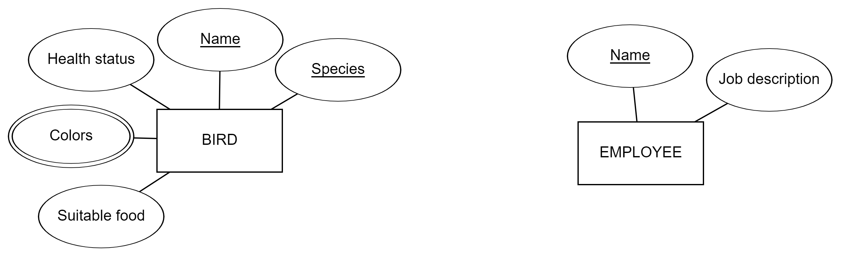
We begin with defining entities and their attributes. We pick substantives and verbs from the description, and fill in rest with your previous understanding and assumptions about the zoo context.
For example,
- Birds have a name, species, colors, current health status and information about suitable food.
- Employees have names and job description (like the manager).
- In the small Zoo, the name is unique to the employee and suitable for primary key [probably].
- Birds are hundreds and may have same names but not within one species [probably]. Primary key is a composite of name and species (no identical pair of values exist in birds).
We continue with defining relationships.
For example,
- An employee feeds many birds.
- An employee may not feed any bird [probably the manager does not feed them]
- During its lifetime, a bird is fed by many employees [probably the Zoo has several employees for feeding]
- There is not necessarily any employee associated with the bird in terms of feeding (in its first minutes in zoo, but eventually the bird will be fed)
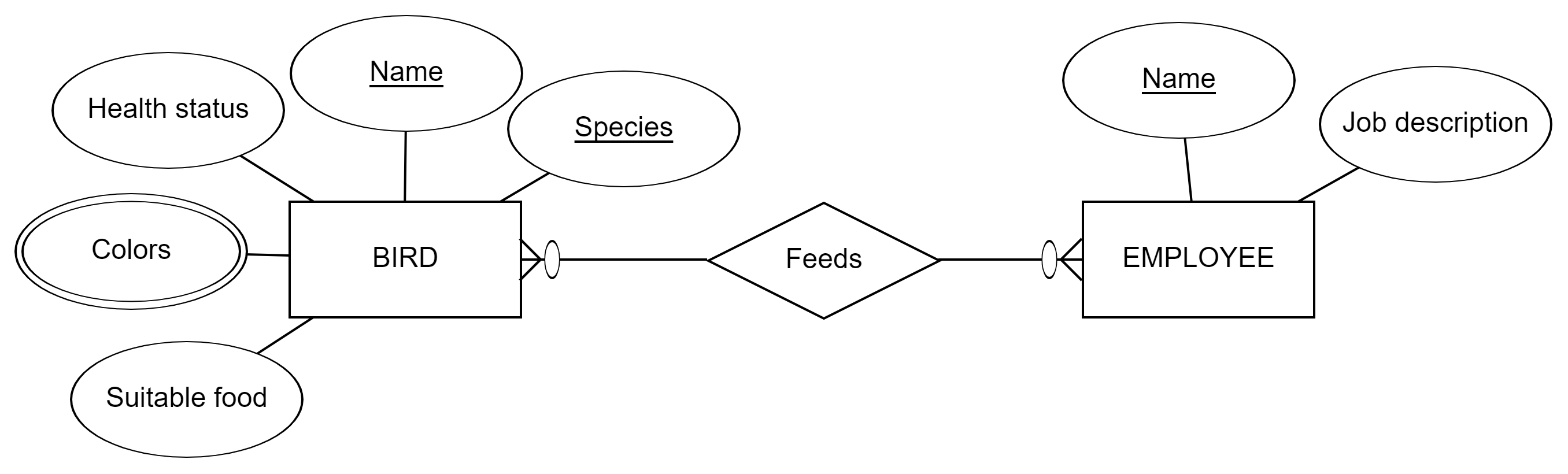
You continue defining the relationship and focus also on attributes that can help in calculating costs of feeding.
- Feedsrelationship should record when the feeding took place. Let’s add date and time attribute to it.
-
To calculate costs, we need to know,
  How long was the feeding and what are the costs of working hours i.e. the duration and the salary.
  How much the given food costs (e.g. per kilogram) and how much it was given i.e. the price and the amount
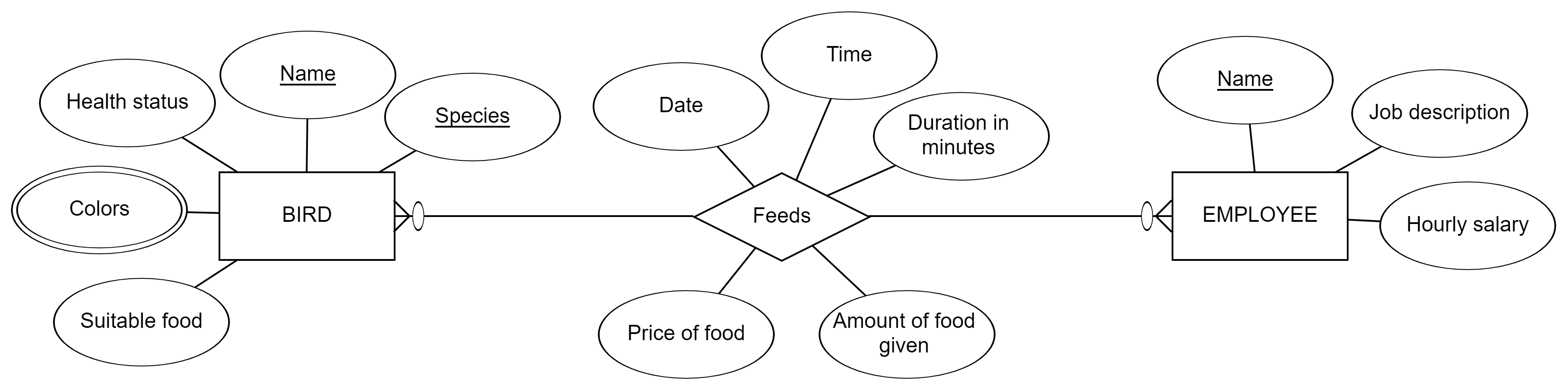
Although our model above holds required data in its attributes and is syntactically correct, we should have noted few alarming design decisions in the above model:
-
As the manager wants information about the feeding, the Feeds relationship must be an important concept in the Zoo context.
Feeds relation has many attributes and even more could be added, which indicates this importance. Such important concepts and sets of interconnected data are usually modelled as entities. -
Feeds-relationship is M:N that fits in ‘a permanent but one-time’ situation. This is not suitable solution based on the requirements and assumptions we made about the context.
 Employees feed birds daily. The same employee feeds the same bird not just once but many times during the system lifecycle. M:N relationship does not allow an employee to feed the same bird twice or vice vers We cannot record that “John the Employee fed Donald the Duck today and yesterday”. Note the difference to situations like “the book was written just once by many authors or the order containing many products was submitted just once”.
 Instead of thinking that employees have a relation to many birds, we should think that employees relate to many feeding events and vice versa. Thus, we design a feeding event entity instead of the relationship.
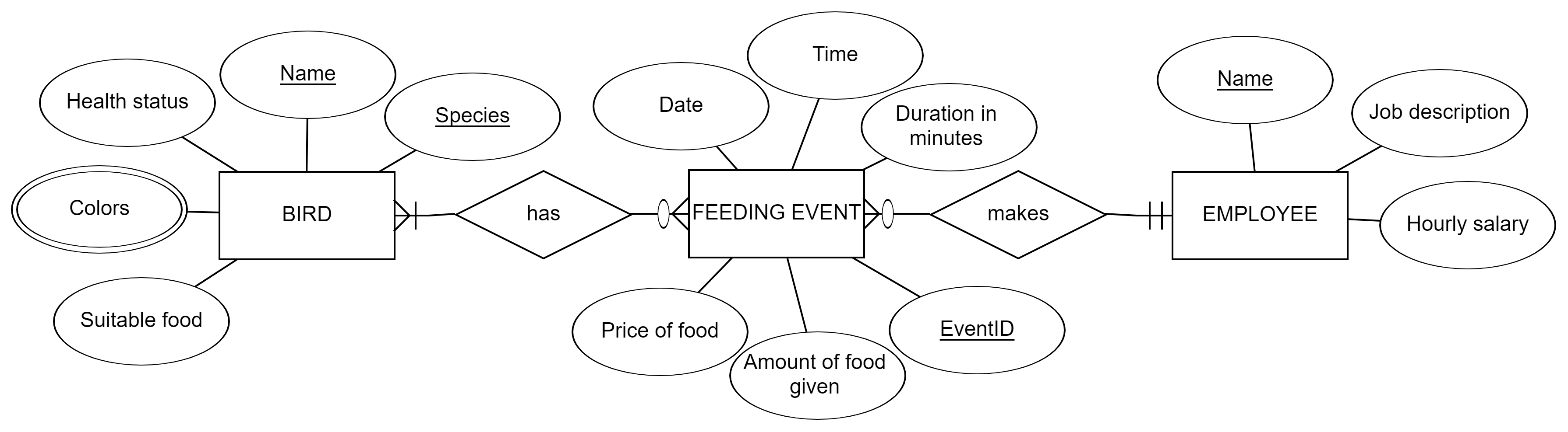
The feeding event is ‘one-time situation’ (like the ordering example above), which can target to many birds. There is no feeding event without any bird or any feeding employee. We assume that the feeding event is made by one employee only. If there are two or more employees performing the feeding events at the same time [in the real world], we will record as many different feeding events with different eventIDs into the database. This cardinality is to some extent also a designer’s choice about the level of details in data.
Now we are almost happy with the initial plan of the database. However, when looking closer to the attributes we find that food-related data is dispersed into many places. The feeding event -entity (like the previous relationship) contains the food price and amount given in a certain event. The given food name (i.e. suitable food) is currently recorded into bird’s data. Dispersing data to different locations may cause update problems in the future. In addition, you may think, what if a bird can eat several different foods and not always the same food is given in the feeding events? In that case, we should add an attribute ‘Given food name’ to the feeding event entity. Then suitable food and given food attributes may repeat the same values, and repeating data is not very good solution either. Therefore, following the definition of an entity, it would be better to gather ‘a set of data’ related to food into Food-entity.
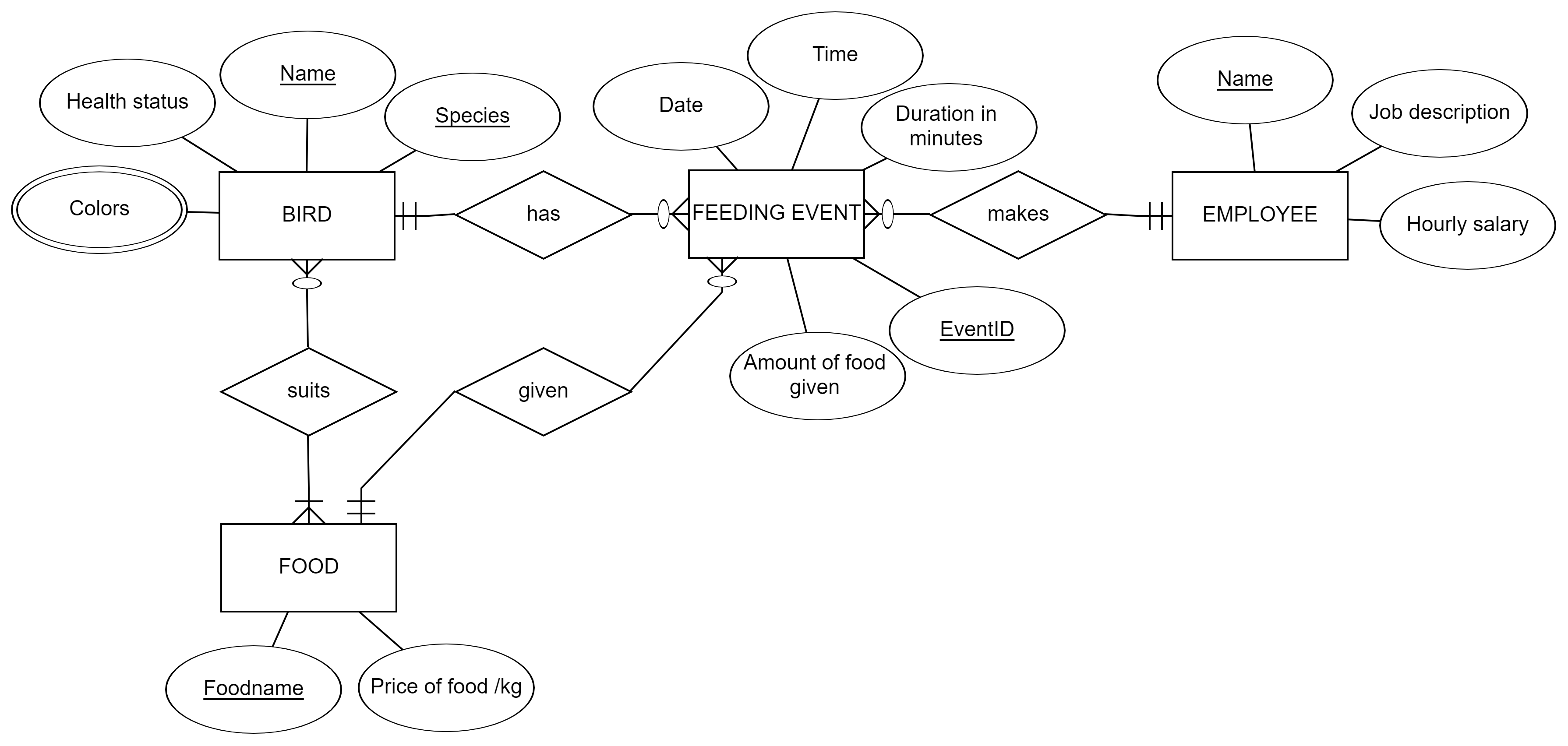
This is our final ER model. Few remarks about the changes made:
- Suitable food attribute was deleted from Bird-entity as the new relationship ‘suits’ to Food entity describes the same thing and allows to record several suitable foods for each bird.
- Price of food attribute was re-placed from Feeding event to Food-entity as the price may not be event-specific and dynamically changing but more static information related to certain type of food.
- Feeding event entity has the relationship ‘given’ to Food entity that denotes the food given in the specific event. The designer made an assumption and a decision regarding the cardinalities: We define the feeding event as being an event where only one food is given (1:N). If two different foods were given to a bird at the same time [in a real-world feeding situation], it would be recorded as two different feeding events as well (similar to employee-event -relationship explained before). The relationship could be M:N also (we should ask the manager!). If it were designed as M:N relationship, the amount of food -attribute has to change place from the Feeding event -entity to the Given-relationship.
- The cardinality of the relationship between the Bird and Feeding event entities was changed to 1:N. This again is a decision that continues the definition of Feeding event entity (i.e. how we understand what is one feeding event in the real world and what it will be in the database?). 1:N was chosen to get the most detailed view on feeding events. The event is now made by one employee for one bird with one type of food. Next, we would consider if our plan is suitable in the Zoo’s working practices, implement the database, develop user interfaces and launch a mobile app to collect data, and finally analyze why birds get sick and how much feeding practices cost.
Drawing ER diagrams
There are many tools that you can use for planning and modelling relational databases. Sometimes ER models are referred in these tools as database models, data models, relational models, ER diagrams, logical models or similar.
Some of the tools are only “drawing tools” and some have further functionality for the whole database implementation. Internet is full of reviews and lists of open-source ER modelling tools. Take a look for example this review: https://www.holistics.io/blog/open-source-data-modeling-tools/
Below, we introduce a light-weight tool that is available online here: https://erdplus.com
Pros:
- Simple to use
- For non-registered users: Easy access with possibility to save and continue with the model; exporting to image
- For registered users: Functions for transforming ER model to implementation with SQL; storing models in the cloud