Design-and-Use-of-Relational-Databases
Content and Goals
In this tutorial, we move onto the tables of a relational database. Related to these we discuss for example, the values of the attributes, keys and referential integrity.
In this tutorial we will learn:
- Properties of tables in relational databases
- Representing attributes and their values in tables
- Key attributes: from superkeys to candidate keys to a primary key, and foreign keys
- Integrity constraints that preserves data quality in relational databases
- How to convert ER model to relational model
Relational model
We are able to model all the same things as we did in ER-model in a relational model. However, many concepts are represented as values in the relational model. This is especially true for the relationships we used with ER-models. For representing these, we use the values of the key attributes. In practice, some database designers, depending on the situation, begin designing from the relational model skipping the ER diagram. That is possible, but let’s learn first what relational model is.
Note! There’s a lot in common between the Relational model and the ER-model. In order not to mix up the used terminology, it’s a good idea to first think of relational model as a completely separate thing and only later on begin comparing these to each other. We will do the comparison and tranformation from the ER model to Relational model in the end of this tutorial. Moreover, do not mix up a relation and a relationship, it is not the same thing.
What is a relation?
We can think of a relation as a named table. One table represents one concept. For example, PERSON, STUDENT, COURSE. A relational database consists of tables and their connections (i.e. relationships). The term ‘relation’ is more mathematical than the term ‘table’ or ‘ relational table’, we will use these terms interchangably and meaning the same in this tutorial.
A table constitutes of columns. Each column is identified by an attribute. For example, First name, Last name, Street address, Zip code, City. We use terms column and attribute for the same purpose.
The table’s (relation’s) name and the attributes form a relation schema, which represents the content of the table as shown in the image below.
The columns are divided into rows to form fields of the table that contain the values. The collection of a row’s values is called a tuple. A tuple is one instance of the relationship. For example, a specific person (in a Person-table).
One field (i.e. cell) can contain only one value, so in relational model the composite and multi-valued attributes need to be divided into separate parts.
In relational model it is possible to form relationships between tables. This is done by “borrowing” the value of the field that identifies the other table’s rows. In this way we are able to present a relationship from one table’s tuple to another table’s tuple. “Borrowing the identifying field” means that usually relationships are created between primary key columns: the table embeds the primary key column of another table (and it is called a foreign key). More about that later.
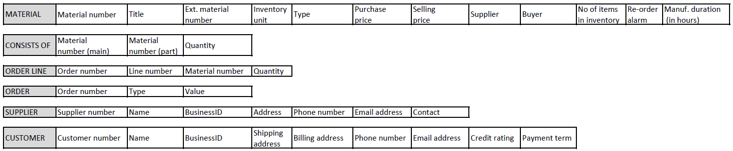
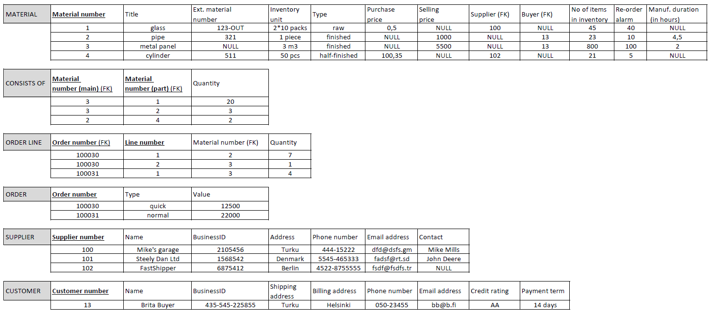
Image below: A relational model for a company that manufactures machine parts. This is a simplified model for client orders.
DESCRIPTION of Case Manufacturer
You have been given the task of modeling the existing production/ordering system of a small, subcontracted machine parts manufacturing company. The company has used a spreadsheet program to structure the data, each thing to be monitored is in its own table. The company keeps track of goods, suppliers, customers and orders. The goods include everything related to the manufacture of machine parts, which are divided into types: finished product, semi-finished product, purchase part, raw material. (Goods are referred as Materials in the current relational model). Semi-finished products and finished products are manufactured by the company itself, while purchased parts and raw materials are obtained from suppliers. For the types of goods manufactured by the company itself, the company keeps a record of what they consist of and how much of each component is needed. Since goods vary from products (finished, semi-finished) to purchased parts and raw materials, they are measured with different units, in relation to which their price or cost is calculated. In connection with the goods, important additional information is also maintained. Inventory quantities are closely monitored and are derived from separate inventory accounting. Too little stock causes production stoppages, and too much stock causes storage space to run out. Because of these, an alarm has been set for the upper and lower limits. There are a reasonable number of suppliers and buyers of the same goods, so it has been decided to record their identification numbers in the goods’ information. Each item takes time to receive, either due to delivery or manufacturing time. The finished product is the sum of all the time spent on the goods needed to make it, plus the time of the own process. There are two types of orders: purchases from suppliers and sales to customers. In the same order, there is a line for each item and their quantities in relation to the item’s storage unit. An address is sufficient for the supplier to contact. Separate billing and delivery addresses are required for the customer. The company checks with the credit rating agency that the customer’s credit information is in order. Both the supplier and the customer have several phone numbers in use, which are useful when things are in a hurry.
Attribute values
Every attribute of a relation has a corresponding domain. It can be said that the attribute names its domain and helps interpret it. The domain consists of a collection of independent, atomic values. All the values in a given domain have the same type. For example, integer, real number, string. They also have a specific form. For example, values that measure units of currency are often represented by real numbers with two decimal precision. The form can also be about the range of values: for example, if we are using binary numbers we could decide that we present them by strings consisting of integers 0 and 1. Also the length can be limited, for example we could decide to use 8 bits (bit 0 or 1). The domains of many attributes can consist of the same values, even if the attributes refer to completely different concepts.
Some additional information can also be applied to the values of the attributes. For example, if null or duplicate values are allowed.
Null value means that this relationships tuple (or row in a table) is missing a value. That is, a null value is not any specific value but rather a way to represent lack of a value (in a table, an empty field of an attribute on a row). Key attributes cannot have null values because this would mean that the value might not be unique (we would not know which instance it is representing or we would be unable to distinguish between two null values). Primary key attribute, like material number in material-table, is unique for each material stored in the database and thus cannot contain null value.
Having null values isn’t necessarily a bad thing. It might be useful to know that a field contains no value. For example, quite a few companies nowadays do not have a fax so the corresponding fax field would not have a value. On the other hand, there might be reasons why certain attributes are not allowed to be null. For example, knowing the company’s financial credibility rating might be a requirement for a client company.
Duplicate values mean that the relation table is allowed to have tuples where the said attribute has same value. Typically attributes used for categorizing the tuples include duplicates (for example, each university course could be categorized as basic or advanced level, and many courses would have same values in this attribute). The key attributes may not contain duplicates because then they would not uniquely identify the tuples.
Key attributes
Key attributes need to be unique (that is, null and duplicate values are not allowed).
They should also be descriptive; for example, a personal identification number or a student id have deliberately been chosen to identify tuples. Often uniqueness can be dependant on context where the information is used. If the relation table does not have any attribute with unique values, a set of attributes can be used as a key if the combination of the values of these attributes is unique for every tuple.
A key or a set of attributes that uniquely defines a relation is called a superkey. A superkey can have attributes that are not necessary for the uniqueness of the key (for example, in addition to personal identification number a superkey could include attribute for street address in an employee table).
A minimal superkey (in the sense that if we remove any more attributes, the key is no longer unique) is called a candidate key. A relation table can have multiple candidate keys.
One of these candidate keys is chosen by the database designer as the primary key for that relation. A good choice for the primary key is often the simplest possible candidate key.
Every table (relation) has to have a primary key.
EXAMPLE
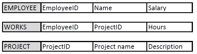
Consider the relational model below. It describes how we store data about our employees and projects and which employees work in which projects.
The primary key of Employee table is EmployeeID, which is unique for each employee we store in this table. Name-column could be another candidate key for the primary key, if we do not store persons with the same name in to our database. Salary is not even a candidate key as people can have same salaries. Both candidate keys are superkeys and minimal superkeys and have only one column. The designer makes a decision and defines EmployeeID as the primary key due to practical limitation of Name-column described above. The primary key is underlined or bolded (or both) or marked otherwise PK.
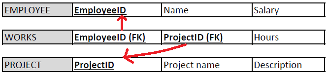
Similarly, ProjectID is the primary key for Project-table.
The primary key of Works-table is a set of attributes, namely EmployeeID and ProjectID together. Why? If we want to store two projects (e.g. projects X and Y) for the same employee (James), we need to create two rows to the Works-table: One with data (James, ProjectX, 15 hours) and another with data (James, ProjectY, 3 hours). Then, EmployeeID column alone is not unique for the rows and requires ProjectID as well. The same holds for ProjectID alone that it is not unique when more than one employee can work in the same project (remember all those thoughts about cardinalities in ER model relationships) .
Foreign keys are attributes or sets of attributes whose values reference the primary key of another relation (table).
They are used to create connections between different relations (tables).
These relations can be used to represent connection between different entities or multi-valued attributes.
The same value of the foreign key can exist in multiple tuples within a table. That is, unlike primary keys, the foreign keys need not be unique.
EXAMPLES
In the Case Manufacturer, Order line -table contains a column Order number, which is a foreign key and refers to the Order number column in the Order-table. Order can contain multiple Order lines, and therefore, the foreign key column Order number in the Order line table can have many same values in different rows (denoting that those rows belong to the same order).
Consider the relational model above about employees and projects. Employee or Project tables do not have foreign keys. Works-table refers to both having two foreign keys EmployeeID and ProjectID, which are also prime attributes.
So,
-
Like in ER models no entities are left alone, in relational models each relation is either referred or referring to another relation.
-
A column can be both a primary key and a foreign key.
We mark foreign keys with FK abbreviation.
In order to search for a specific piece of information in a relational model often requires data (attribute values) from multiple different relations. We are often looking for an answer to a question that cannot be answered by one relation alone. Finding the answer in these cases is achieved by using the foreign keys and the values of tuples.
EXAMPLE
Search names of all such employees who work in project X and whose salary is over 5000 euros per month.
First we look for tuples in PROJECT relation with values representing the project X in ProjectID column.
Next, we look at the WORKS relation and search project X values in ProjectID column (foreign key). Each matching value gives us on the same row the EmployeeID representing the employee working in that project. Now that we have the employee numbers we search through the EMPLOYEE table and select the ones with the value of salary attribute at over 5000 euros. Finally, we list the name attributes of the tuples with these salaries from the employee table.
This is also the principle how the query language (SQL) works in relational databases.
Inserting and deleting records
When changes are made to a database based on the relational model, we must make sure that the state of the database is still valid after the changes are made. Excess or missing data can make the database inoperable or give incorrect replies to queries. Constraints describe the criteria that the changes need to comply with in order to avoid breaking the database. Attributes need to comply with the constraints placed on the values of the tables columns and the key attributes need to be unique. Integrity constraints and the referential integrity are in turn related to the values assigned to primary and foreign keys. In addition, we can define semantic restrictions related to the business use case the database is modelling.
The key constraint requires that the key of the relation must not contain duplicates, as the key must be able to uniquely identify a row of the relational table in any legal state of the database.
An entity integrity constraint means that its primary key value must not be null; otherwise, it would not be possible to uniquely identify tuples if there are more than one tuple missing the primary key value.
The referential integrity constraint applies to consistency between the tables. If an attribute (or a set of attributes) appears in a table, which conceptually references another attribute (or a set of) either in the same or another table, the value of the attribute of the first mentioned table must either be represented in the referenced table or, alternatively, be null. That is, a tuple in one relation that refers to another relation must refer to an existing tuple in that relation.
In addition, there can also be semantic restrictions, such as preventing the possibility that the employee would work more than X hours per week or increasing the employee’s salary above his supervisor’s salary.
Update operations Update operations include inserting, deleting and updating tuples. In the context of this tutorial, the insertion and deletion operations will be considered.
Insert operations In the insert operation, a new row (= tuple, record) is added to the relational table.
An insertion attempt can violate the relational model in four different ways:
- The value of an attribute may be illegal, i.e. of the wrong data type or outside the allowed value range. For example, the number of enrolled students in the course exceeds the set maximum value.
- The uniqueness of the key is violated if the value of the key of the tuple being inserted already exists another tuple. For example, the course with the same name is added to database.
- The integrity constraint of the entity is violated if the tuple being inserted is missing the value of the key attribute. For example, the course without a name is added to database.
- The referential integrity is violated if no corresponding key is found for the value of the tuples foreign key being inserted from the attribute (or set of attributes) referred to by the value. For example, the course with a reference to an unknown (missing) teacher is added.
Below is a relational model of the Manufacturer with primary and foreign keys marked and with some example data added. The next exercises are based on this model and data content.
Delete operation In the delete operation, a tuple belonging to a relational table is removed.
When deleting tuples from a relation, the referential integrity of the database may be broken if the tuple in question is referenced (foreign keys) in other relations. For example, if we try to delete a (row of a) teacher who is referenced as a lecturer in an ongoing course, the referential integrity constraint will likely prevent the deletion.
Transforming ER model to Relational model
ER-model »» Relational model
Entity type »» Relation table representing the entity type
1:1 or 1:N relation »» Foreign key (or a separate relation table)
M:N relation »» Relation table with two foreign keys from both entities that are also primary keys
Relation of degree n (n>2) »» Relation table with n foreign keys
Simple attribute »» Attribute
Composite attribute »» A set of simple attributes
Multi-valued attribute A of Entity E »» Relation table which primary key is the combination of E’s primary key and a single value of attribute A
An algorithm that transforms an ER model into relational model.
By following this algorithm, the ER model can be systematically converted into a relational model without losing data.
STAGE 1: For each strong entity type E of the ER model, let’s establish a relational table R, where all the simple attributes of E are placed. Composite attributes are represented as partitioned simple attributes. Let’s choose one of the key attributes of E as the primary key of R. If necessary, the primary key can consist of a set of multiple attributes.
STAGE 2: For each weak entity type W, a separate relational table R is created, where all the simple attributes related to that entity are collected. Again with the weak entities, composite attributes are presented partitioned into simple attributes. In addition, the primary key Z of the owner entity of W is included in the table. The combination of the partial key of W and Z is chosen as the main key of the table. In the worst case, the partial key of W consists of the combination of all its own attributes.
STAGE 3: For each connection R with a cardinality of type 1:1, the tables S and T participating in the relationship are determined. If either one of the tables is required to totally participate in the relationship R, that table is chosen as table S (this way we avoid storing unnecessary NULL values). After this, the primary key of table T is assgined as the foreign key of table S, and in addition, all the attributes specific to relation R are also exported to table S.
STAGE 4: For each relation R between tables S and T with a cardinality of 1:N, the table with the cardinality N is selected as the table S. The primary key of table T (i.e. the 1 side of R) and all the attributes of the relationship are placed in table S.
STAGE 5: For each relation R, with cardinality M:N, a new table S must be established in the database. The attributes forming the primary key of the two tables U and V participating in the relationship are placed as attributes in the table S. The combination of these attributes forms the primary key of the table S. In addition, all the attributes of the relation R are placed in S.
STAGE 6: For each multi-valued attribute A of the entity E in the ER model, a new relation table S must be created. In that table, an attribute B must be placed to represent each separate value of A. In addition, the primary key Z of table R describing entity E must be placed as a foreign key in table S in order to know which tuple of R the tuples of table S are related to. The primary key of table S thus consists of the combination of attributes Z and B.
STAGE 7: For each relation R of at least degree 3, a new relational table S is created, in which the primary key attributes of all the tables E participating in the relation R are placed. In addition, additional attributes specific to R are placed in S. The primary key of table S is formed by the combination of the primary keys of all the tables E, excluding those of cardinality 1.
In short,
STAGE 1: Normal entities: Create a table with the selected primary key (PK)
STAGE 2: Weak entities: Create table. The primary key is a composite key consisting of the weak entity’s partial key + strong entity’s primary key (which is a foreign key FK as well)
STAGE 3: 1:1 relationships: Create a foreign key (FK) to the table which has the mandatory participation (the one that has no null values)
STAGE 4: 1:N relationships: Create a foreign key (FK) to the table with multiplicity (N) participation
STAGE 5: N:M relationships: Create a table. The primary key is a composite from all the participating entities. Those are also foreign keys (FK) referring to the participating entities.
STAGE 6: Multivalued attributes: Create table named as the attribute + the primary key is a composite consisting the entity’s primary key and attribute’s own name
STAGE 7: Relations with 3 or more entities: Create table. The primary key is a composite consisting participating entities’ keys (and FKs as in N:M).
Composite attribute: Add only its sub-components to table as columns.
The Zoo – ER to Relational model example step by step
Remember this ER model from the last tutorial?
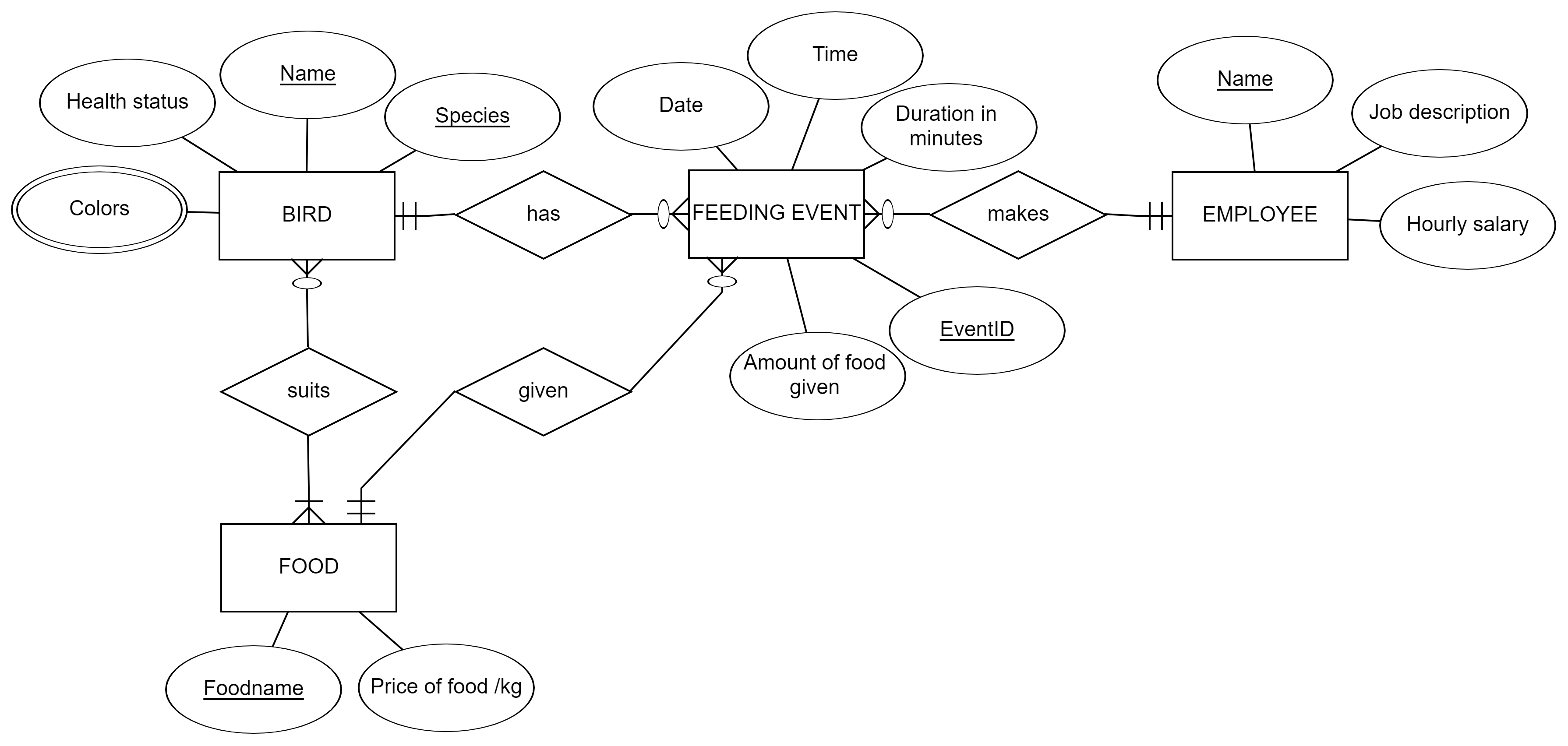
Let’s go towards the database implementation for the Zoo and change this model to a relational schema. We use the algorithm, the seven stages described earlier to transform the model. Below, stages are explained in text. In the video, you can see how to do the transformation with our modelling tool (http://erdplus.com)
Stage 1: Entities Bird, Feeding_event, Employee and Food are represented as tables with their attributes as columns except Colors attribute.
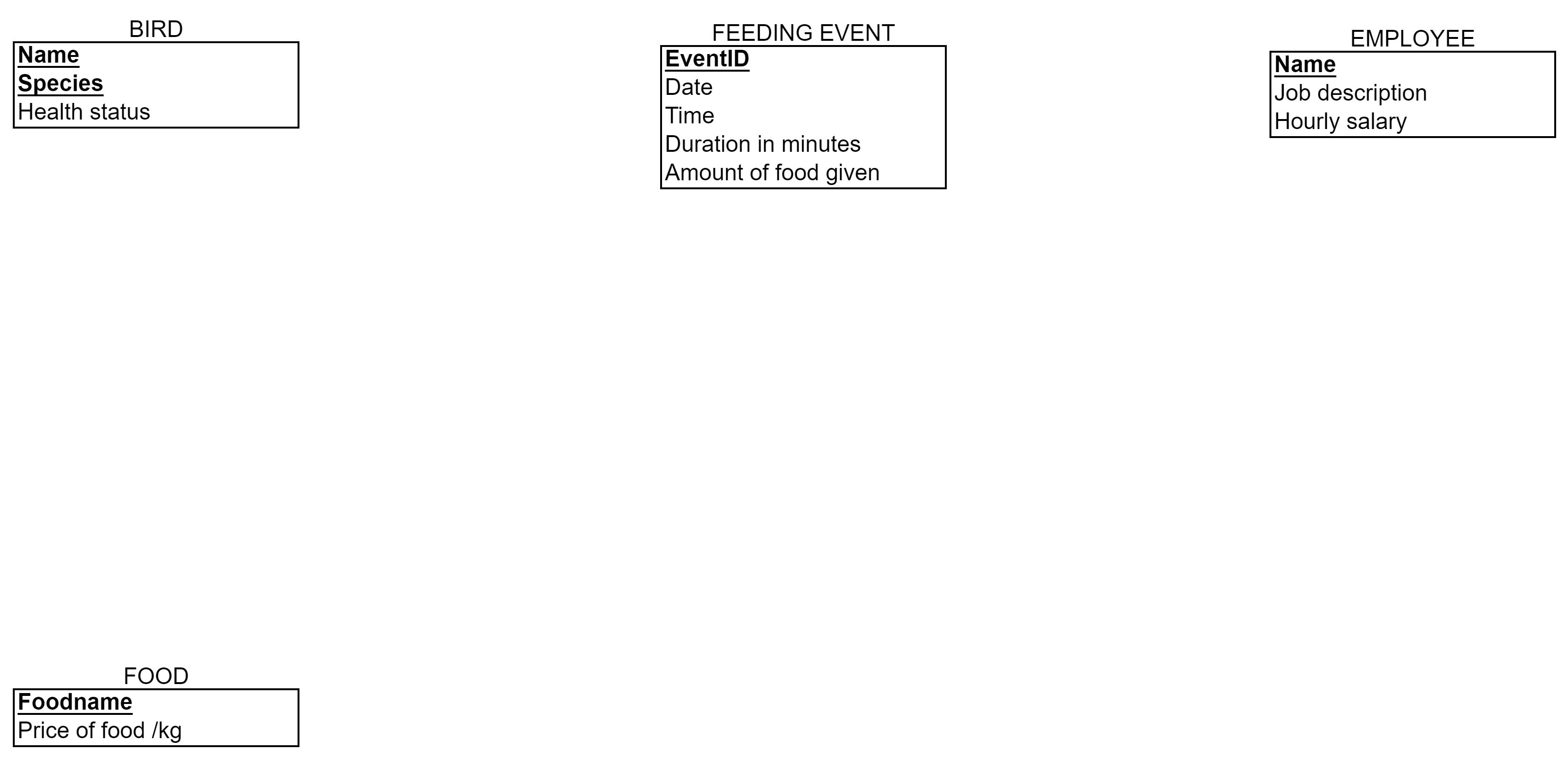
Stage 2: No weak entities, no changes
Stage 3: No 1:1 relationships, no changes
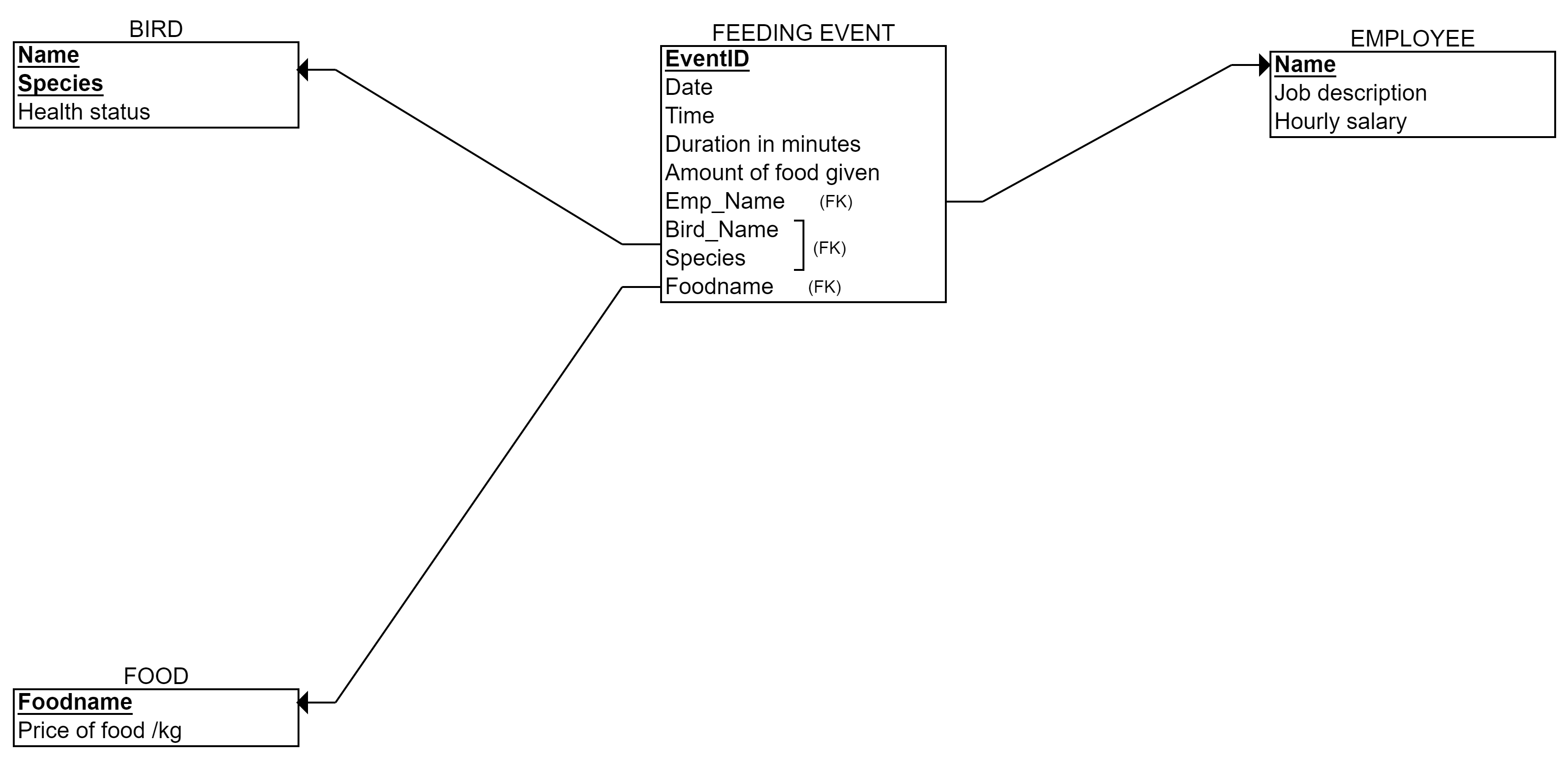
Stage 4: Three 1:N relationships: has, makes and given. The relationship end with only one instance participation gives the foreign key to the other end. In this case, we create three foreign keys to Feeding_event -table: Employee’s name, Foodname, and Birds’ name and Bird’s species.
Stage 5: One N:M relationship suits. We create a new table called Birds’_Foods (I prefer to mention both tables, but you can choose the best naming). The primary key is: Bird’s name, Bird’s species, and Foodname. These are foreign keys as well. No other columns in the table.
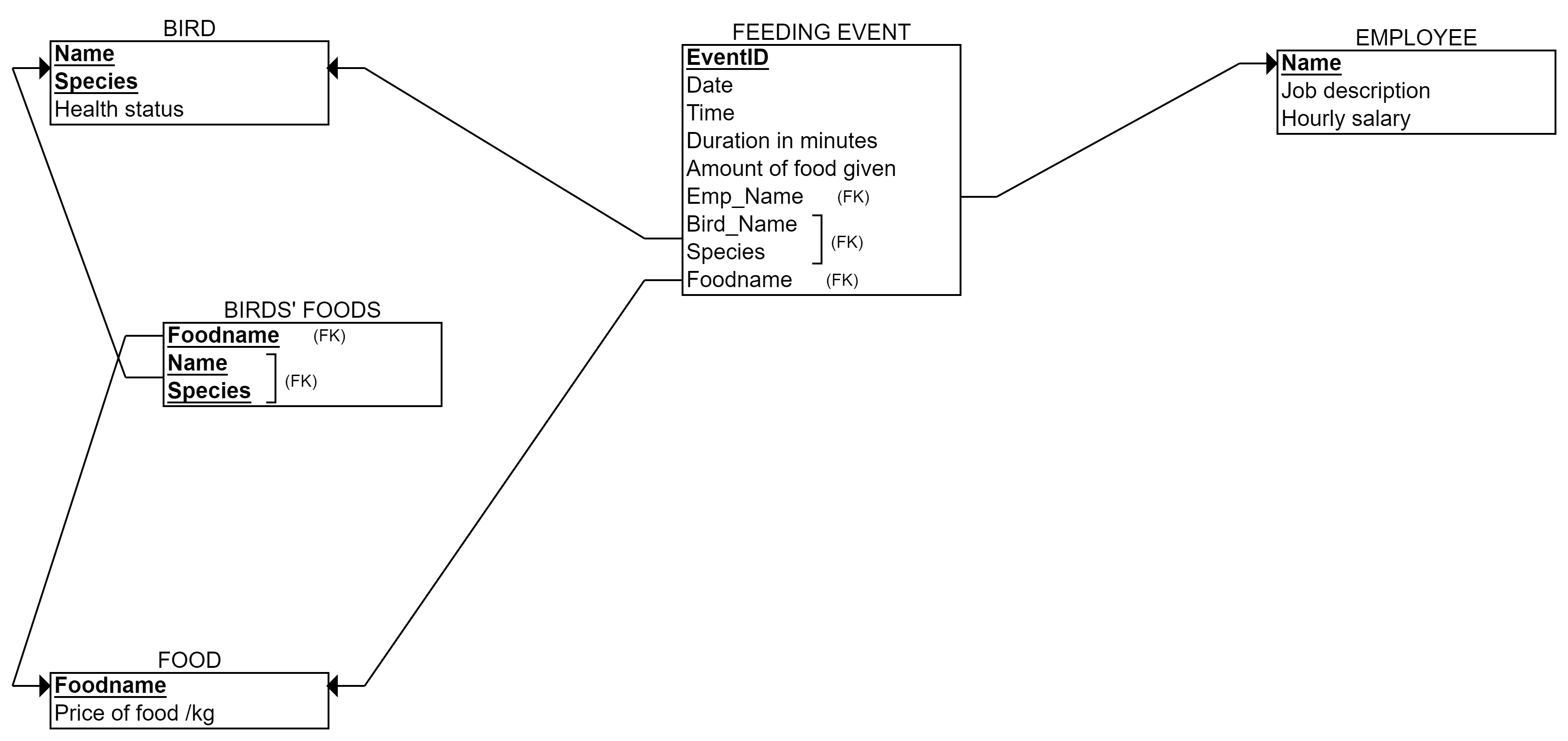
Stage 6: One multivalued attribute Colors. We create a new table called Birds’_Colors (naming up to you again, but I like to refer to the table it is attached to). The primary key is: Bird’s name, Bird’s species, and Color. Name and Species is a foreign key to the Bird-table.
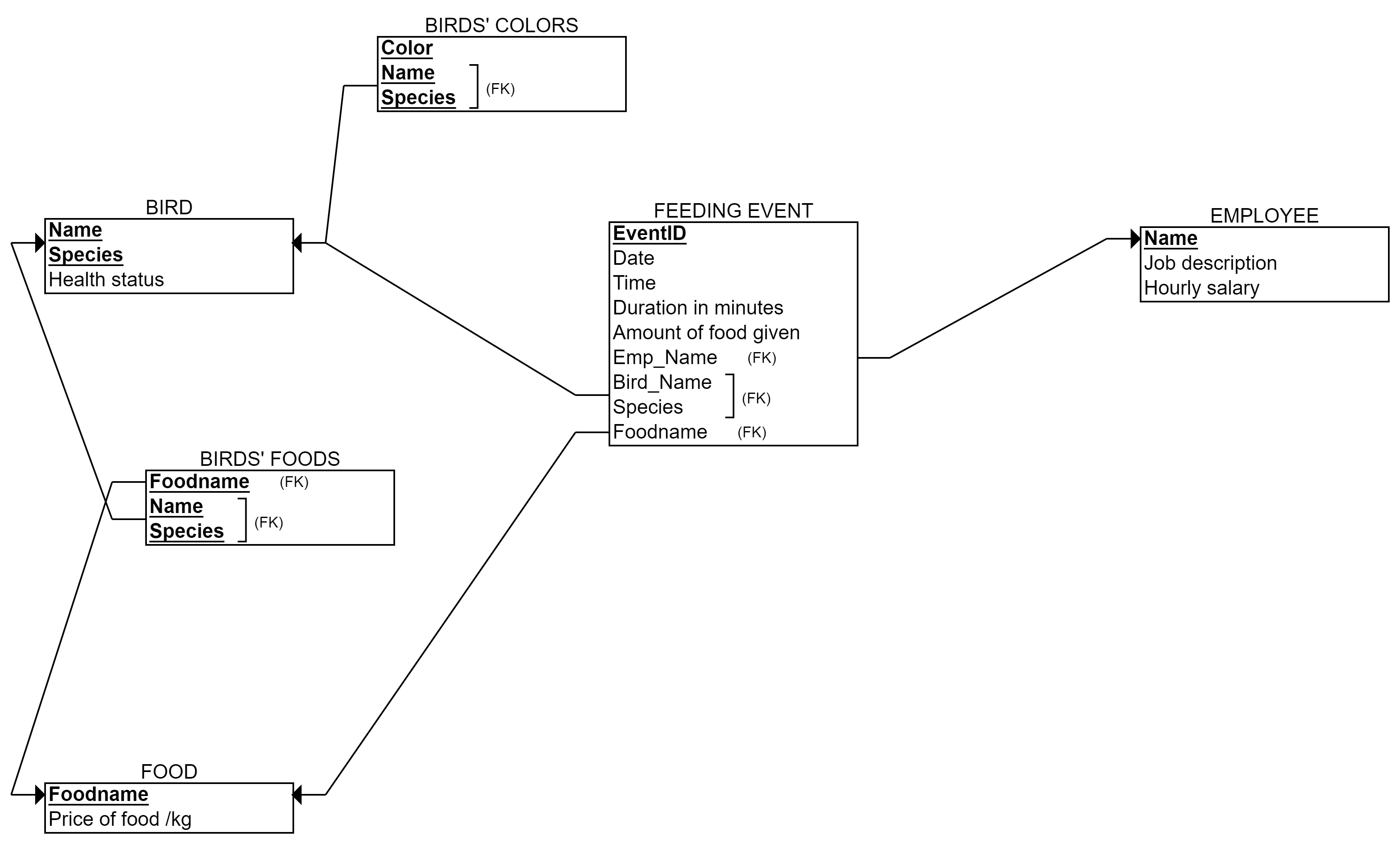
Stage 7: No relationships with 3 or more entities, no changes.
That is our final relational model above.
Next take a look at the video how to create this model wih the online tool.
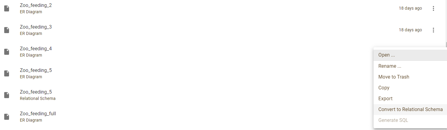
If you have created your ER model with the erdplus or other tool, one option is to use converting function to translate it to a relational model. As a registered user of erdplus.com, you can select “Convert to relational schema” (see the image below).
However, it is always good to check the result! The stages of the algorithm that these functions base on, are not always producing the most feasible relational model in practice. If the ER is complex or has somehow unnatural or personally creative solutions, the automatically created relational model may become false or unnecessarily complex. Thus, the database designer should walk through the final relational model.